Tag Archives: MediaPipe

Bringing artworks to life with AR

Posted by Richard Adem, UX Engineer at Google Arts & Culture

What is Art Filter?

One of the best ways to learn about global culture is by trying on famous art pieces using Google’s Augmented Reality technology on your mobile device. What does it feel like to wear a three thousand year old necklace, put on a sixteenth century Japanese helmet or don pearl earrings and pose in a Vermeer?

Google Arts & Culture have created a new feature called Art Filter allowing everyone to learn about culturally significant art pieces from around the world and put themselves inside famous paintings, normally safely displayed in a museum.

We teamed up with the MediaPipe team, which offers cross-platform, customizable ML solutions to combine ML with rendering to generate stunning visuals.

Working closely with the MediaPipe team to utilize their face mesh and 3D face transform allowed us to create custom effects for each of the artifacts we had chosen, and easily display them on as part of the Google Arts & Culture iOS and Android app.

gif of the art filter feature

Figure 1. The Art Filter feature.

The Challenges

We selected five iconic cultural treasures from around the world:

Given their diverse formats or textures each artwork or object required special approaches to bring it to life in AR.

gif of user wearing jewelry on art filter feature

Figure 2. User wearing the jewelry from Johannes Vermeer's "Girl with a Pearl Earring" - Mauritshuis museum, Hague.

Creating 3D objects that can be viewed from all sides, using 2D references.

Some of the artwork we selected are 2D paintings and we wanted everyone to immerse themselves in the paintings. Our team of 3D artists and designers took high resolution gigapixel images from Google Arts & Culture and projected them onto 3D meshes to texture them. We also extended the 2D textures all the way around the 3D meshes while maintaining the style of the original artist. This means that when you turn your head the previously hidden parts of the piece are viewable from every angle, mimicking how the object would look in real-life.

Gif of the Van Gogh Self-Portrait filter

Figure 3. The Van Gogh Self-Portrait filter - Musée d’Orsay, Paris.

Our cultural partners were immensely helpful during the creation of Art Filter. They have sourced a huge amount of reference images allowing us to reproduce the pieces accurately using photographs from different angles, to help them appear to fit into the “real world” in AR (using size comparisons).

Layering elements of the effect along with the image of the user.

Art Filter takes an image of the user from their device’s camera and uses that to generate a 3D mesh of the user’s face. All processing of user images or video feeds is run entirely on device. We do not use this feature to identify or collect any personal biometric data; the feature cannot be used to identify an individual.

The image is then reused to texture the face mesh, generated in real-time on-device with MediaPipe Face Mesh, representing it in the virtual 3D world within the device. We then add virtual 2D and 3D layers around the face to complete the effect. The Tengu Helmet, for example, sits on top of the face mesh in 3D and is “attached” to the face mesh so it moves around when the user moves their head around. The Vermeer earrings with a headscarf and Frida Kahlo’s necklace are attached to the user’s image in a similar way. The Van Gogh effect works slightly differently since we still use a mesh of the user’s face but this time we apply a texture from the painting.

We use 2D elements to complete the scene as well, such as the backgrounds in the Kahlo and Van Gogh paintings. These were created by carefully separating the painting subjects from the background then placing them behind the user in 3D. You may notice that Van Gogh’s body is also 2D, shown as a “billboard” so that it always faces the camera.

Figure 4. Creating the 3D mesh showing layers and masks.

Figure 4. Creating the 3D mesh showing layers and masks.

Using shaders for different materials such as the metal helmet.

To create a realistic looking material we used “Physically Based” Rendering shaders. You can see this on the Tengu helmet, it has a bumpy surface that is affected by the real life light captured by the device. This requires creating extra textures, texture maps, for the effect that uses colors to represent how bumpy or shiny the 3D object should appear. Texture maps look like bright pink and blue images but tell the renderer about tiny details on the surface of the object without creating any extra polygons, which can slow down the frame rate of the feature.

Figure 5. User wearing Helmet with Tengu Mask and Crows - The Metropolitan Museum of Art

Figure 5. User wearing Helmet with Tengu Mask and Crows - The Metropolitan Museum of Art.

Conclusion

We hope you enjoy the collection we have created in Art Filter. Please visit and try for yourself! You can also explore more amazing ML features with Google Arts & Culture such as Art Selfie and Art Transfer.

We hope to bring many more filters to the feature and are looking forward to new features from MediaPipe.

Control your Mirru prosthesis with MediaPipe hand tracking

Guest post by the Engineering teams at Mirru and Tweag

What is the Mirru App?

Mirru App logo

Mirru is a free and open source Android app under development with which one can control robotic prosthetic hands via hand tracking. With our app, a user can instantly mirror grips from their sound hand onto a robotic one, which could be 3D-printed and self-assembled at low cost. With Mirru, we want to provide a cheap, intuitive and open end-to-end alternative to existing, costly, cumbersome and proprietary technology.

A demonstration of using MediaPipe hand tracking to move a robotic hand’s fingers with the Mirru app.

Figure 1: A demonstration of using MediaPipe hand tracking to move a robotic hand’s fingers with the Mirru app.

The Mirru team is a collaboration between Violeta López and Vladimir Hermand, two independent designers and technologists currently based in Paris. To kickstart the project, the team took part in Tweag’s Open Source Fellowship program which provided funding, mentorship and data engineering expertise from one of their engineers, Dorran Howell. The fellowship helped get Mirru launched from the ground-up.

Our goal for the 3-month fellowship was to develop an initial version of the Android app that can control any bluetooth open source hand using computer vision techniques, and make the app available for free on the Google Play store so anyone can print their own hand, assemble it, and download the app. With the help of MediaPipe, we were able to quickly prototype our app without having to build our own machine learning model, as we didn’t have the resources or training data to do so.

Why use hand tracking?

Using your phone and a front-facing camera with hand tracking opens up a new, affordable, accessible, and versatile way to control prosthetics.

Let's say I'm a left hand amputee who owns a robotic prosthesis. Every day, I need my prosthetic hand to actuate a lot of different grip patterns. For example, I need to use a pinch or tripod grip to pick up small objects, or a fist grip to pick up objects like a fruit or a cup. I change and execute these grip patterns via myoelectric muscle sensors that allow me to, for example, open and close a grip by flexing and unflexing my upper limb muscles. These myoelectric muscle sensors are the main interface between my body and the prosthesis.

However, living with them is not as easy as it seems. Controlling the myoelectric sensors can take a lot of time to get used to, and many never do. It can also be quite expensive to get these sensors fitted by a prosthetist, especially for people in developing countries or anyone without health insurance. Finally, the number of grips on many devices currently on the market is limited to less than ten, and only few models come with ways to create custom grips, which are often cumbersome.

Mirru provides an alternative interface. Using just their phone, a tool many have access to, a user can digitally mirror their sound hand in real-time and communicate with their prosthesis in an intuitive way. This removes the expensive need to be fitted by a prosthetist and enables the user to quickly program an unlimited amount of grips. For now, Mirru stays away from electromyography altogether as reliable muscle sensors are expensive. The programmed grips therefore need to be triggered via the android phone, which is why this first version of our app is more suited for activities like sweeping, holding a book while reading it, or holding a cup or shopping bag. In the future we hope to combine myoelectric sensors with hand tracking to get the benefits of both.

Programming a grip with the Mirru app looks like the following: Let’s say that I want to grab an object with my robotic hand. I bring my prosthesis near the object and I then form the desired grip with my sound hand in front of my android phone and Mirru mirrors it in real-time to the prosthesis. I then lock my prosthesis into this new grip and free up my vsound hand. Finally I might save this grip for later use and add it to my library of grips.

A user tester using hand-tracking on their phone to program their prosthesis’s grip to pick up a measuring tape and measure with the other hand.

Figure 2: A user tester using hand-tracking on their phone to program their prosthesis’s grip to pick up a measuring tape and measure with the other hand.

The Brunel Hand and the Mirru Arduino Sketch

In order to accomplish our goal of allowing as many people as possible to print, assemble, and control their own hand, we designed the Mirru android app to be compatible with any robotic hand that is controlled by a bluetooth-enabled Arduino board and servo motors.

For our project, we printed and assembled an open source robotic hand called the Brunel Hand made by Open Bionics. First, we 3D printed the Brunel Hand’s 3D printable files that are made available under the CC Attribution-Sharealike 4.0 International License. We then bought the necessary servos, springs, and screws to assemble the hand. In combination with printing and buying the servos, the hand costs around €500 to purchase and assemble.

The Brunel Hand comes with myoelectric-based firmware and a PCB board developed by Open Bionics, but since the hand is in essence just 4 servo motors, any microcontroller could be used. We ended up using an Adafruit ESP32 feather board for its bluetooth capabilities and created an Arduino sketch that can be downloaded, customized, and uploaded for anyone who is printing and assembling their own hand. They could then download the Mirru app to use as the control-interface for their printed hand.

Hand-tracking with MediaPipe

There are many computer vision solutions available for hand tracking that could be used for this project, but we needed a fast, open source solution that didn’t require us to train our own model, and that could be used reliably on a portable device such as a phone.

MediaPipe provides great out of the box support for hand tracking, and since we didn’t have the training data or resources available to create a model from scratch, it was perfect for our team. We were able to build the Android example apps easily and were excited to find that the performance was promising. Even better, no tweaking on the ready-made hand tracking model or the graphs was necessary, as the hand landmark model provided all the necessary outputs for our prototype.

When testing the prosthesis on real users, we were happy to hear that many of them were impressed with how fast the app was able to translate their movements, and that nothing else exists on the market that allows you to make custom grips as fast and on-the-fly.

A user tester demonstrates how quickly the MediaPipe hand-tracking can translate her moving fingers to the movement of her prosthesis’s fingers.

Figure 3: A user tester demonstrates how quickly the MediaPipe hand-tracking can translate her moving fingers to the movement of her prosthesis’s fingers.

Translating 3D MediaPipe points into inputs for Robotics

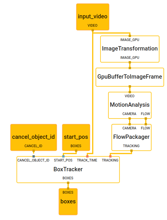
To achieve the goals of the Mirru app, we need to use hand tracking to independently control each finger of the Brunel Hand in real-time. In the Brunel Hand, the index, middle, and ring fingers are actuated using servos that move at an angle from 0 to 180 degrees; 0 means the finger is fully upright and 180 means the finger is fully flexed down. As we lacked adequate training data to create a model from scratch that could calculate these servo angles for us, we opted to use a heuristic to relate the default hand tracking landmark outputs to the inputs required by our hardware for an initial version of our prototype.

In the lab testing the translation of the outputs to inputs with the app and the prototype.

Figure 4: In the lab testing the translation of the outputs to inputs with the app and the prototype.

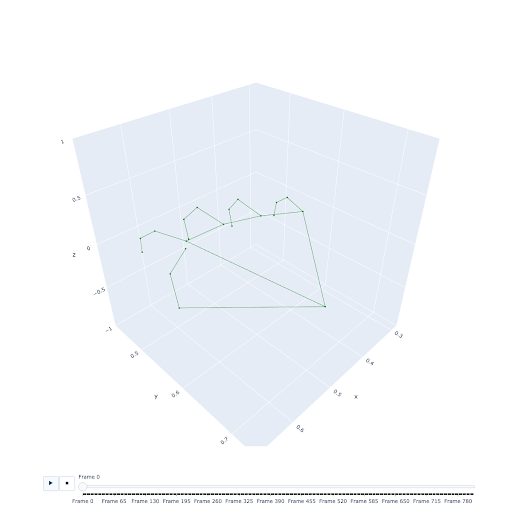
We were initially unsure whether the estimated depth (Z) coordinate in the 3D landmarks would be accurate enough for the translation of inputs or if we would be limited to working in 2D. As an initial step, we recorded an example dataset and spun up a visualization of the points in a Jupyter Notebook with Plotly. We were immediately impressed by the quality and accuracy of the coordinates, considering that the technology only uses a single camera without any depth sensors. As noted in the MediaPipe documentation, The Z coordinates have a slightly different scale than the X/Y coordinates, but this didn’t seem to pose a significant challenge for our prototype.

A data visualization of the hand made up of 21 3D hand landmarks provided by MediaPipe.

Figure 5: A data visualization of the hand made up of 21 3D hand landmarks provided by MediaPipe.

Given the accuracy of the 3D landmarks, we opted to use a calculation in 3D for relating landmark outputs to the inputs required by the prosthesis. In our approach, we calculate the acute angles of the fingers in relation to the palm by calculating the angle between the finger direction and the normal of the plane defined by the palm. An angle of 0° corresponds to maximum closure of the finger, and an angle of 180° indicates a fully extended finger. We were able to calculate the finger direction by calculating the vector from the landmark at the base of the fingers to the landmark on the tip of the fingers.

Diagram showing the 3D landmarks and which ones we used to calculate the finger direction vector, the palm normal, and the angle that both form.

Figure 6: Diagram showing the 3D landmarks and which ones we used to calculate the finger direction vector, the palm normal, and the angle that both form.

We calculate the palm normal by selecting three points in the plane of the palm. Using Landmark 0 as the reference point, we calculate the vectors for side 1 and side 2, and compute the cross product of those vectors to give us the palm normal. Finally, we compute the angle of the finger direction and the palm normal. This returns an angle in radians that we use to calculate degrees.

We had to do some extra processing to match the degrees of freedom for the thumb on our prosthetic hand. The thumb moves in more complex ways than the rest of the fingers. In order to get our app to work with the thumb, we did similar calculations for thumb direction and the palm normal, but we used different landmarks.

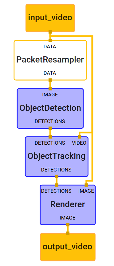
Once we do the calculation of the servo angles on the android phone, we send those values via bluetooth to the Arduino board, and the Arduino board moves the servos to the proper position. Due to some noise in the model outputs, we add a smoothing step to the pipeline, which is important so that the movements of the robotic fingers aren’t too jittery for precise grips.

A user tester makes a pinch grip on her prosthesis with the Mirru app.

Figure 7: A user tester makes a pinch grip on her prosthesis with the Mirru app.

Summary

The Mirru app and Mirru Arduino Sketch are designed to allow anyone to control an open source prosthesis with their sound hand and an Android phone. This is a novel and frugal alternative to muscle sensors, and MediaPipe has proven that it is the right tool for the essential hand tracking component of the full application. The Mirru team was able to get started quickly with MediaPipe’s out of the box solutions without having to gather any training data or having to design a model from scratch. The speed of the real-time translation from hand tracking points to the robotic hand has especially excited all of our users in our testing sessions and opens up many possibilities for the future of prostheses.

We see exciting potential for combining the MediaPipe hand tracking features with existing myoelectric prostheses which could open powerful and advanced ways to create and save custom prosthesis grips in real-time. Also, with the help of MediaPipe, we have been able to provide an open source alternative to proprietary prostheses without the need for myoelectric sensors or a visit to a prosthetist, at a cost that is much lower than what is already on the market, and whose source code can be customized and built-upon by other developers. Our team is excited to see what other ideas the open source community might come up with, and to see what hand tracking can bring to users and manufacturers of prostheses.

As for the current state of the Mirru application, we have yet to implement the possibility of recording and saving moving gestures that are longer sequences compared to the static grip positions. For example, imagine being able to record the movement of the fingers to play a bass line on a piano, like a loopable animated gif. There is a realm of possibilities for prostheses that is waiting to be explored, and we’re really happy that MediaPipe gives us access to it.

We are looking for contributors. If you have ideas or comments about this application, please reach out to [email protected], or visit our GitHub.

This blog post is curated by Igor Kibalchich, ML Research Product Manager at Google AI.

SignAll SDK: Sign language interface using MediaPipe is now available for developers

A guest post by the Engineering team at SignAll | Twitter handle | MediaPipe team

Please note that the information, uses, and applications expressed in the below post are solely those of our guest author, SignAll.

SignAll SDK: Sign language interface using MediaPipe is now available for developers

When Google published the first versions of its on-device hand tracking technology in MediaPipe, the work could serve as a basis for developers to build sign language recognition solutions into their own apps. Later updates to this hand tracking solution have further improved its accuracy where other technologies have fallen short (Figure 1).

Illustrating MediaPipe’s improvement over time: hand skeleton tracking output of an older version (2020.02.10) and the latest version (2020.12.16).

Figure 1. Illustrating MediaPipe’s improvement over time: hand skeleton tracking output of an older version (2020.02.10) and the latest version (2020.12.16). This handshape is used in sign language frequently, but often missed because of the lack of representation in training datasets.
Watch the full video

SignAll is a startup working on sign language translation technology. Its mission is to make sign language interpretation universally available, both through communication between Deaf and hearing parties, and between Deaf individuals and computers. The SignAll’s products, which are used nationwide in the US for both communications and education, employ a complex multi-camera setup and gloves with colored markers. While sign languages’ complexity goes far beyond handshapes (facial features, body, grammar, etc.), it is true that the accurate tracking of the hands has been a huge obstacle in the first layer of processing – computer vision. MediaPipe unlocked the possibility to offer SignAll’s solutions not only glove free, but also by using a single camera. SignAll has just announced the availability of the first SDK of its kind, so developers can now enable sign language input in their apps.

The company recently published an interactive educational app in the App Store, that lets the user practice signing with immediate feedback, this app also serves as a demonstration of the possibilities with the SDK.

SignAll with MediaPipe Hands

Our system uses several layers for sign recognition, and each one uses more and more abstract data. The low-level layer extracts crucial hand, body, and face data from 2D and 3D cameras. In our first implementation, this layer detects the colors of the gloves and creates 3D hand data. Replacing this with MediaPipe Hands (supplemented by the MediaPipe Pose and MediaPipe Face Mesh) has been a game changer for using our system without gloves or special lighting.

Demo of our SignAll SDK developed using MediaPipe asking how are you
Demo greeting of our SignAll SDK developed using MediaPipe

Figure 2. Demo of our SignAll SDK developed using MediaPipe

As mentioned earlier, we use multiple cameras with depth sensors which are calibrated in the real world. This allows for a more accurate 3D world space than that of a local camera or tensor spaces, but requires the use of hand landmark detection for each camera. The cameras are placed distinctly to each other in position and orientation so the hands are visible more frequently, as one hand might cover the other from one camera but not necessarily from the others.

Corrected 3D hand shape based on three cameras. Due to the unique orientation, the detection from the front camera is wrong, but the side camera can correct the result.

Figure 3. Corrected 3D hand shape based on three cameras. Due to the unique orientation, the detection from the front camera is wrong, but the side camera can correct the result.

The next step is to filter and smooth the data to replicate the precise measurements offered by our colored glove markers. Although SignAll’s markers are different from the landmarks given by MediaPipe, we used our hand model to generate colored markers from landmarks. Therefore, the new mocap data is fully compatible with the previous one.

Although we are focused mainly on the hands, we also integrated MediaPipe Pose and MediaPipe Face Mesh. The pose landmarks provide accurate hand position information, even when touching or close to each other.

While the two versions of mocap are compatible, the nature of the artifacts is different: direct measure of each marker and simulated markers from a globally detected hand. Due to this discrepancy, we had to refine the parameters on higher levels. On the other hand, we could still use our huge sign database for the gloveless configuration. By replacing the low-level data and refining our higher-level data, we could test our system without gloves. Going gloveless can be a huge step for using our sign recognition technology easily worldwide.

Demonstration of compatible mocap from different low-level trackings.

Figure 4. Demonstration of compatible mocap from different low-level trackings. The right side is without gloves; the left side is with gloves. This compatibility enables the usage of SignAll’s meticulously labeled dataset of 300,000+ sign language videos to be used for the training of recognition models based on different low-level data. Watch the full video

The SignAll system using MediaPipe framework

After integrating MediaPipe Hands into our system, we also wanted to take advantage of the customization and scaling opportunities provided by the MediaPipe framework on multiple platforms. This allowed us to not only prototype our research state methods in Python, but also deliver our end-user solutions for Windows, iOS, Android, and even the Web. Thanks to the similarities between our module graph system and the calculator graph of MediaPipe, our existing processing units can be reused in this new framework with minor modifications. With that said, the extended platform set also comes with other challenges, like using only a single 2D camera in most cases instead of a calibrated multi-camera system.

The models, algorithms and techniques we have used were mostly developed to work on our mocap data interpreted in the 3D global world. The data extracted from a single-camera setup, of course, cannot be as detailed. That is the reason we had to make some adjustments to our implementations, fine-tune the algorithms and add some extra logic (e.g., dynamically adapting to the changes of space resulted by the hand-held camera use-case). Luckily, the MediaPipe framework enables us to implement the core processing units in C++, so we can still benefit from the runtime-optimized core solutions we previously developed.

Some higher-level models trained on 3D data also needed to be re-trained in order to perform better on the data originating from a single 2D source. The MediaPipe landmarks are defined by 3D coordinates, which makes it possible to reuse the existing training methods and concepts. On the other hand, the 2D information is more directly extracted and therefore more stable than the third coordinate, which was taken into consideration while designing the training modifications.

Luckily, it is not necessary to make an entirely new data recording for this purpose. We can still use our huge video database annotated in great detail. The preprocessed mocap data we can extract from our recordings and interpreted in the 3D world can be used to simulate hand, skeleton, or face landmark detections in any virtual camera view.

Among the data on virtual camera views, we also use traditional 2D recordings in sufficient proportion to cover the unique noise characteristics of the landmark detections. Thanks to having most of these types of data in advance, we can focus on the most exciting part - trying the latest techniques and training new models.

Summary

The advancement made possible by MediaPipe enabled SignAll to change its model. In addition to offering all-in-one products for sign language education and translation, SignAll is now starting to offer an SDK for developers. The capabilities of this SDK depend on the type of the camera or cameras being used and the available computational capacity. The possible functions enabled by using the SDK vary from launching video calls by signing the contact’s name (watch a demo here), adding addresses into navigation by signing (as a counterpart to speech input), or ordering food on a fast-food restaurant’s kiosk or drive-thru. With its mission to make sign language an alternative everywhere that voice can be used, SignAll is excited to see more and more apps implementing this feature.

We are eager to try future updates of MediaPipe, which could bring us closer to our ultimate goal of having our solutions available for everyone on any device. The most awaited update is the ability to build custom MediaPipe graphs and add our own calculators for web-based solutions aided by the WebAssembly technology, so websites will be able to use a new level of accessibility features for Deaf visitors.

MediaPipe 3D Face Transform

Posted by Kanstantsin Sokal, Software Engineer, MediaPipe team

Earlier this year, the MediaPipe Team released the Face Mesh solution, which estimates the approximate 3D face shape via 468 landmarks in real-time on mobile devices. In this blog, we introduce a new face transform estimation module that establishes a researcher- and developer-friendly semantic API useful for determining the 3D face pose and attaching virtual objects (like glasses, hats or masks) to a face.

The new module establishes a metric 3D space and uses the landmark screen positions to estimate common 3D face primitives, including a face pose transformation matrix and a triangular face mesh. Under the hood, a lightweight statistical analysis method called Procrustes Analysis is employed to drive a robust, performant and portable logic. The analysis runs on CPU and has a minimal speed/memory footprint on top of the original Face Mesh solution.

MediaPipe image

Figure 1: An example of virtual mask and glasses effects, based on the MediaPipe Face Mesh solution.

Introduction

The MediaPipe Face Landmark Model performs a single-camera face landmark detection in the screen coordinate space: the X- and Y- coordinates are normalized screen coordinates, while the Z coordinate is relative and is scaled as the X coordinate under the weak perspective projection camera model. While this format is well-suited for some applications, it does not directly enable crucial features like aligning a virtual 3D object with a detected face.

The newly introduced module moves away from the screen coordinate space towards a metric 3D space and provides the necessary primitives to handle a detected face as a regular 3D object. By design, you'll be able to use a perspective camera to project the final 3D scene back into the screen coordinate space with a guarantee that the face landmark positions are not changed.

Metric 3D Space

The Metric 3D space established within the new module is a right-handed orthonormal metric 3D coordinate space. Within the space, there is a virtual perspective camera located at the space origin and pointed in the negative direction of the Z-axis. It is assumed that the input camera frames are observed by exactly this virtual camera and therefore its parameters are later used to convert the screen landmark coordinates back into the Metric 3D space. The virtual camera parameters can be set freely, however for better results it is advised to set them as close to the real physical camera parameters as possible.

MediaPipe image

Figure 2: A visualization of multiple key elements in the metric 3D space. Created in Cinema 4D

Canonical Face Model

The Canonical Face Model is a static 3D model of a human face, which follows the 3D face landmark topology of the MediaPipe Face Landmark Model. The model bears two important functions:

  • Defines metric units: the scale of the canonical face model defines the metric units of the Metric 3D space. A metric unit used by the default canonical face model is a centimeter;
  • Bridges static and runtime spaces: the face pose transformation matrix is - in fact - a linear map from the canonical face model into the runtime face landmark set estimated on each frame. This way, virtual 3D assets modeled around the canonical face model can be aligned with a tracked face by applying the face pose transformation matrix to them.

Face Transform Estimation

The face transform estimation pipeline is a key component, responsible for estimating face transform data within the Metric 3D space. On each frame, the following steps are executed in the given order:

  • Face landmark screen coordinates are converted into the Metric 3D space coordinates;
  • Face pose transformation matrix is estimated as a rigid linear mapping from the canonical face metric landmark set into the runtime face metric landmark set in a way that minimizes a difference between the two;
  • A face mesh is created using the runtime face metric landmarks as the vertex positions (XYZ), while both the vertex texture coordinates (UV) and the triangular topology are inherited from the canonical face model.

Effect Renderer

The Effect Renderer is a component, which serves as a working example of a face effect renderer. It targets the OpenGL ES 2.0 API to enable a real-time performance on mobile devices and supports the following rendering modes:

  • 3D object rendering mode: a virtual object is aligned with a detected face to emulate an object attached to the face (example: glasses);
  • Face mesh rendering mode: a texture is stretched on top of the face mesh surface to emulate a face painting technique.

In both rendering modes, the face mesh is first rendered as an occluder straight into the depth buffer. This step helps to create a more believable effect via hiding invisible elements behind the face surface.

MediaPipe image

Figure 3: An example of face effects rendered by the Face Effect Renderer.

Using Face Transform Module

The face transform estimation module is available as a part of the MediaPipe Face Mesh solution. It comes with face effect application examples, available as graphs and mobile apps on Android or iOS. If you wish to go beyond examples, the module contains generic calculators and subgraphs - those can be flexibly applied to solve specific use cases in any MediaPipe graph. For more information, please visit our documentation.

Follow MediaPipe

We look forward to publishing more blog posts related to new MediaPipe pipeline examples and features. Please follow the MediaPipe label on Google Developers Blog and Google Developers twitter account (@googledevs).

Acknowledgements

We would like to thank Chuo-Ling Chang, Ming Guang Yong, Jiuqiang Tang, Gregory Karpiak, Siarhei Kazakou, Matsvei Zhdanovich and Matthias Grundman for contributing to this blog post.

Instant Motion Tracking with MediaPipe

Posted by Vikram Sharma, Software Engineering Intern; Jianing Wei, Staff Software Engineer; Tyler Mullen, Senior Software Engineer

Augmented Reality (AR) technology creates fun, engaging, and immersive user experiences. The ability to perform AR tracking across devices and platforms, without initialization, remains important for powering AR applications at scale.

Today, we are excited to release the Instant Motion Tracking solution in MediaPipe. It is built upon the MediaPipe Box Tracking solution we released previously. With Instant Motion Tracking, you can easily place fun virtual 2D and 3D content on static or moving surfaces, allowing them to seamlessly interact with the real world. This technology also powered MotionStills AR. Along with the library, we are releasing an open source Android application to showcase its capabilities. In this application, a user simply taps the camera viewfinder in order to place virtual 3D objects and GIF animations, augmenting the real-world environment.

gif of instant motion tracking in MediaPipe gif of instant motion tracking in MediaPipe

Instant Motion Tracking in MediaPipe

Instant Motion Tracking

The Instant Motion Tracking solution provides the capability to seamlessly place virtual content on static or motion surfaces in the real world. To achieve that, we provide the six degrees of freedom tracking with relative scale in the form of rotation and translation matrices. This tracking information is then used in the rendering system to overlay virtual content on camera streams to create immersive AR experiences.

The core concept behind Instant Motion Tracking is to decouple the camera’s translation and rotation estimation, treating them instead as independent optimization problems. This approach enables AR tracking across devices and platforms without initialization or calibration. We do this by first finding the 3D camera translation using only the visual signals from the camera. This involves estimating the target region's apparent 2D translation and relative scale across frames. The process can be illustrated with a simple pinhole camera model, relating translation and scale of an object in the image plane to the final 3D translation.

image

By finding the change in relative size of our tracked region from view position V1 to V2, we can estimate the relative change in distance from the camera.

Next, we obtain the device’s 3D rotation from its built-in IMU (Inertial Measurement Unit) sensor. By combining this translation and rotation data, we can track a target region with six degrees of freedom at relative scale. This information allows for the placement of virtual content on any system with a camera and IMU functionality, and is calibration free. For more details on Instant Motion Tracking, please refer to our paper.

A MediaPipe Pipeline for Instant Motion Tracking

A diagram of Instant Motion Tracking pipeline is shown below, consisting of four major components: a Sticker Manager module, a Region Tracking module, a Matrices Manager module, and lastly a Rendering System. Each of the components consists of MediaPipe calculators or subgraphs.

Diagram

Diagram of Instant Motion Tracking Pipeline

The Sticker Manager accepts sticker data from the application and produces initial anchors (tracked region information) based on user taps, and user gesture controls for every sticker object. Initial anchors are then sent to our Region Tracking module to generate tracked anchors. The Matrices Manager combines this data with our device’s rotation matrix to produce six degrees-of-freedom poses as model matrices. After integrating any user-specified transforms like asset scaling, our final poses are forwarded to the Rendering System to render all virtual objects overlaid on the camera frame to produce the output AR frame.

Using the Instant Motion Tracking Solution

The Instant Motion Tracking solution is easy to use by leveraging the MediaPipe cross-platform framework. With camera frames, device rotation matrix, and anchor positions (screen coordinates) as input, the MediaPipe graph produces AR renderings for each frame, providing engaging experiences. If you wish to integrate this Instant Motion Tracking library with your system or application, please visit our documentation to build your own AR experiences on any device with IMU functionality and a camera sensor.

Augmenting The World with 3D Stickers and GIFs

Instant Motion Tracking solution allows bringing both 3D stickers and GIF animations into Augmented Reality experiences. GIFs are rendered on flat 3D billboards placed in the world, introducing fun and immersive experiences with animated content blended into the real environment.Try it for yourself!

Demonstration of GIF placement in 3D Demonstration of GIF placement in 3D

Demonstration of GIF placement in 3D

MediaPipe Instant Motion Tracking is already helping PixelShift.AI, a startup applying cutting-edge vision technologies to facilitate video content creation, to track virtual characters seamlessly in the view-finder for a realistic experience. Building upon Instant Motion Tracking’s high-quality pose estimation, PixelShift.AI enables VTubers to create mixed reality experiences with web technologies. The product is going to be released to the broader VTuber community later this year.

Instant

Instant Motion Tracking helps PixelShift.AI create mixed reality experiences

Follow MediaPipe

We look forward to publishing more blog posts related to new MediaPipe pipeline examples and features. Please follow the MediaPipe label on Google Developers Blog and Google Developers twitter account (@googledevs).

Acknowledgement

We would like to thank Vikram Sharma, Jianing Wei, Tyler Mullen, Chuo-Ling Chang, Ming Guang Yong, Jiuqiang Tang, Siarhei Kazakou, Genzhi Ye, Camillo Lugaresi, Buck Bourdon, and Matthias Grundman for their contributions to this release.

MediaPipe KNIFT: Template-based Feature Matching

Posted by Zhicheng Wang and Genzhi Ye, MediaPipe team

Image Feature Correspondence with KNIFT

In many computer vision applications, a crucial building block is to establish reliable correspondences between different views of an object or scene, forming the foundation for approaches like template matching, image retrieval and structure from motion. Correspondences are usually computed by extracting distinctive view-invariant features such as SIFT or ORB from images. The ability to reliably establish such correspondences enables applications like image stitching to create panoramas or template matching for object recognition in videos (see Figure 1).

Today, we are announcing KNIFT (Keypoint Neural Invariant Feature Transform), a general purpose local feature descriptor similar to SIFT or ORB. Likewise, KNIFT is also a compact vector representation of local image patches that is invariant to uniform scaling, orientation, and illumination changes. However unlike SIFT or ORB, which were engineered with heuristics, KNIFT is an embedding learned directly from a large number of corresponding local patches extracted from nearby video frames. This data driven approach implicitly encodes complex, real-world spatial transformations and lighting changes in the embedding. As a result, the KNIFT feature descriptor appears to be more robust, not only to affine distortions, but to some degree of perspective distortions as well. We are releasing an implementation of KNIFT in MediaPipe and a KNIFT-based template matching demo in the next section to get you started.

Figure 1: Matching a real Stop Sign with a Stop Sign template using KNIFT.

Training Method

In Machine Learning, loosely speaking, training an embedding means finding a mapping that can translate a high dimensional vector, such as an image patch, to a relatively lower dimensional vector, such as a feature descriptor. Ideally, this mapping should have the following property: image patches around a real-world point should have the same or very similar descriptors across different views or illumination changes. We have found real world videos a good source of such corresponding image patches as training data (See Figure 3 and 4) and we use the well-established Triplet Loss (see Figure 2) to train such an embedding. Each triplet consists of an anchor (denoted by a), a positive (p), and a negative (n) feature vector extracted from the corresponding image patches, and d() denotes the Euclidean distance in the feature space.

Figure 2: Triplet Loss Function.

Figure 2: Triplet Loss Function.

Training Data

The training triplets are extracted from all ~1500 video clips in the publicly available YouTube UGC Dataset. We first use an existing heuristically-engineered local feature detector to detect keypoints and compute the affine transform between two frames with a high accuracy (see Figure 4). Then we use this correspondence to find keypoint pairs and extract the patches around these keypoints. Note that the newly identified keypoints may include those that were detected but rejected by geometric verification in the first step. For each pair of matched patches, we randomly apply some form of data augmentation (e.g. random rotation or brightness adjustment) to construct the anchor-positive pair. Finally, we randomly pick an arbitrary patch from another video as the negative to finish the construction of this triplet (see Figure 5).

Figure 3: An example video clip from which we extract training triplets.

Figure 4: Finding frame correspondence using existing local features.

Figure 5: (Top to bottom) Anchor, positive and negative patches.

Hard-negative Triplet Mining

To improve model quality, we use the same hard-negative triplet mining method used by FaceNet training. We first train a base model with randomly selected triplets. Then we implement a pipeline that uses the base model to find semi-hard-negative samples (d(a,p) < d(a,n) < d(a,p)+margin) for each anchor-positive pair (Figure 6). After mixing the randomly selected triplets and hard-negative triplets, we re-train the model with this improved data.

Figure 6: (Top to bottom) Anchor, positive and semi-hard negative patches.

Model Architecture

From model architecture exploration, we have found that a relatively small architecture is sufficient to achieve decent quality, so we use a lightweight version of the Inception architecture as the KNIFT model backbone. The resulting KNIFT descriptor is a 40-dimensional float vector. For more model details, please refer to the KNIFT model card.

Benchmark

We benchmark the KNIFT model inference speed on various devices (computing 200 features) and list them in Table 1.

Table 1: KNIFT performance benchmark.

Table 1: KNIFT performance benchmark.

Quality-wise, we compare the average number of keypoints matched by KNIFT and by ORB (OpenCV implementation) respectively on an in-house benchmark (Table 2). There are many publicly available image matching benchmarks, e.g. 2020 Image Matching Benchmark, but most of them focus on matching landmarks across large perspective changes in relatively high resolution images, and the tasks often require computing thousands of keypoints. In contrast, since we designed KNIFT for matching objects in large scale (i.e. billions of images) online image retrieval tasks, we devised our benchmark to focus on low cost and high precision driven use cases, i.e. 100-200 keypoints computed per image and only ~10 matching keypoints needed for reliably determining a match. In addition, to illustrate the fine-grained performance characteristics of a feature descriptor, we divide and categorize the benchmark set by object types (e.g. 2D planar surface) and image pair relations (e.g. large size difference). In table 2, we compare the average number of keypoints matched by KNIFT and by ORB respectively in each category, based on the same 200 keypoint locations detected in each image by the oFast detector that comes with the ORB implementation in OpenCV.

Table 2: KNIFT vs ORB average number of matched keypoints.

From Table 2, we can see that KNIFT consistently matches more keypoints than ORB by a large margin in every category. Here we acknowledge the fact that KNIFT (40-d float) is considerably larger than ORB (32-d char) and this can have an effort on matching quality. Nevertheless, most local feature benchmarks do not take descriptor size into account so we will follow the convention here.

To make it easy for developers to try KNIFT in MediaPIpe, we have built a local-feature-based template matching solution (see implementation details using MediaPipe in the next section). As a side effect, we can demonstrate the matching quality between KNIFT and ORB visually in side-by-side comparisons like Figure 7 and 9.

Figure 7: Example of “matching 2D planar surface”. (Left) KNIFT 183/240, (Right) ORB 133/240.

In Figure 7, we choose a typical U.S. Stop Sign image from Google Image Search as the template and attempt to match it with the Stop Sign in this video. This example falls into the “matching 2D planar surface” category in Table 2. Using the same 200 keypoint locations detected by oFast and the same RANSAC setting, we show that KNIFT is successful at matching the Stop Sign in 183 frames out of a total of 240 frames. In comparison, ORB matches 133 frames.

Figure 8: Example of “matching 3D untextured object”. Two template images from different views.

Figure 9: Example of “matching 3D untextured object”. (Left) KNIFT 89/150, (Right) ORB 37/150.

Figure 9 shows another matching performance comparison on an example from the “matching 3D untextured object” category in Table 2. Since this example involves large perspective changes of untextured surfaces, which is known to be challenging for local feature descriptors, we use template images from two different views (shown in Figure 8) to improve the matching performance. Again, using the same keypoint locations and RANSAC setting, we show that KNIFT is successful at matching 89 frames out of a total of 150 frames while ORB matches 37 frames.

KNIFT-based Template Matching in MediaPipe

We are releasing the aforementioned template matching solution based on KNIFT in MediaPipe, which is capable of identifying pre-defined image templates and precisely localizing recognized templates on the camera image. There are 3 major components in the template-matching MediaPipe graph shown below:

  • FeatureDetectorCalculator: a calculator that consumes image frames and performs OpenCV oFast detector on the input image and outputs keypoint locations. Moreover, this calculator is also responsible for cropping patches around each keypoint with rotation and scale info and stacking them into a vector for the downstream calculator to process.
  • TfLiteInferenceCalculator with KNIFT model: a calculator that loads the KNIFT tflite model and performs model inference. The input tensor shape is (200, 32, 32, 1), indicating 200 32x32 local patches. The output tensor shape is (200, 40), indicating 200 40-dimensional feature descriptors. By default, the calculator runs the TFLite XNNPACK delegate, but users have the option to select the regular CPU delegate to run at a reduced speed.
  • BoxDetectorCalculator: a calculator that takes pre-computed keypoint locations and KNIFT descriptors and performs feature matching between the current frame and multiple template images. The output of this calculator is a list of TimedBoxProto, which contains the unique id and location of each box as a quadrilateral on the image. Aside from the classic homography RANSAC algorithm, we also apply a perspective transform verification step to ensure that the output quadrilateral does not result in too much skew or a weird shape.

Figure 10: MediaPipe graph of the demo

Demo

In this demo, we chose three different denominations ($1, $5, $20) of U.S. dollar bills as templates and attempted to match them to various real world dollar bills in videos. We resized each input frame to 640x480 pixels, ran the oFast detector to detect 200 keypoints, and used KNIFT to extract feature descriptors from each 32x32 local image patch surrounding these keypoints. We then performed template matching between these video frames and the KNIFT features extracted from the dollar bill templates. This demo runs at 20 FPS on a Pixel 2 Phone CPU with XNNPACK.

Figure 11: Matching different U.S. dollar bills using KNIFT.

Build Your Own Templates

We have provided a set of built-in planar templates in our demo. To make it easy for users to try their own templates, we also provide a tool to build such an index with user generated templates. index_building.pbtxt is a MediaPipe graph that accepts as its input a directory path containing a set of template images. Users can use this graph to compute KNIFT descriptors for all template images (which will be stored in a single file) by 1) replacing the index_proto_filename field in the main graph and the BUILD file and 2) rebuilding the APK file. For step-by-step instructions on how we created the dollar bill demo shown above, please refer to this documentation.

Acknowledgements

We would like to thank Jiuqiang Tang, Chuo-Ling Chang, Dan Gnanapragasam‎, Howard Zhou, Jianing Wei and Ming Guang Yong for contributing to this blog post.

Alfred Camera: Smart camera features using MediaPipe

Guest post by the Engineering team at Alfred Camera

Please note that the information, uses, and applications expressed in the below post are solely those of our guest author, Alfred Camera.

In this article, we’d like to give you a short overview of Alfred Camera and our experience of using MediaPipe to transform our moving object feature, and how MediaPipe has helped to get things easier to achieve our goals.

What is Alfred Camera?

AlfredCamera logo

Fig.1 Alfred Camera Logo

Alfred Camera is a smart home app for both Android and iOS devices, with over 15 million downloads worldwide. By downloading the app, users are able to turn their spare phones into security cameras and monitors directly, which allows them to watch their homes, shops, pets anytime. The mission of Alfred Camera is to provide affordable home security so that everyone can find peace of mind in this busy world.

The Alfred Camera team is composed of professionals in various fields, including an engineering team with several machine learning and computer vision experts. Our aim is to integrate AI technology into devices that are accessible to everyone.

Machine Learning in Alfred Camera

Alfred Camera currently has a feature called Moving Object Detection, which continuously uses the device’s camera to monitor a target scene. Once it identifies a moving object in the area, the app will begin recording the video and send notifications to the device owner. The machine learning models for detection are hand-crafted and trained by our team using TensorFlow, and run on TensorFlow Lite with good performance even on mid-tier devices. This is important because the app is leveraging old phones and we'd like the feature to reach as many users as possible.

The Challenges

We had started building our AI features at Alfred Camera since 2017. In order to have a solid foundation to support our AI feature requirements for the coming years, we decided to rebuild our real-time video analysis pipeline. At the beginning of the project, the goals were to create a new pipeline which should be 1) modular enough so we could swap core algorithms easily with minimal changes in other parts of the pipeline, 2) having GPU acceleration designed in place, 3) cross-platform as much as possible so there’s no need to create/maintain separate implementations for different platforms. Based on the goals, we had surveyed several open source projects that had the potential but we ended up using none of them as they either fell short on the features or were not providing the readiness/stabilities that we were looking for.

We started a small team to prototype on those goals first for the Android platform. What came later were some tough challenges way above what we originally anticipated. We ran into several major design changes as some key design basics were overlooked. We needed to implement some utilities to do things that sounded trivial but required significant effort to make it right and fast. Dealing with asynchronous processing also led us into a bunch of timing issues, which took the team quite some effort to address. Not to mention debugging on real devices was extremely inefficient and painful.

Things didn't just stop here. Our product is also on iOS and we had to tackle these challenges once again. Moreover, discrepancies in the behavior between the platform-specific implementations introduced additional issues that we needed to resolve.

Even though we finally managed to get the implementations to the confidence level we wanted, that was not a very pleasant experience and we have never stopped thinking if there is a better option.

MediaPipe - A Game Changer

Google open sourced MediaPipe project in June 2019 and it immediately caught our attention. We were surprised by how it is perfectly aligned with the previous goals we set, and has functionalities that could not have been developed with the amount of engineering resources we had as a small company.

We immediately decided to start an evaluation project by building a new product feature directly using MediaPipe to see if it could live up to all the promises.

Migrating to MediaPipe

To start the evaluation, we decided to migrate our existing moving object feature to see what exactly MediaPipe can do.

Our current Moving Object Detection pipeline consists of the following main components:

  • (Moving) Object Detection Model
    As explained earlier, a TensorFlow Lite model trained by our team, tailored to run on mid-tier devices.
  • Low-light Detection and Low-light Filter
    Calculate the average luminance of the scene, and based on the result conditionally process the incoming frames to intensify the brightness of the pixels to let our users see things in the dark. We are also controlling whether we should run the detection or not as the moving object detection model does not work properly when the frame has been processed by the filter.
  • Motion Detection
    Sending frames through Moving Object Detection still consumes a significant amount of power even with a small model like the one we created. Running inferences continuously does not seem to be a good idea as most of the time there may not be any moving object in front of the camera. We decided to implement a gating mechanism where the frames are only being sent to the Moving Object Detection model based on the movements detected from the scene. The detection is done mainly by calculating the differences between two frames with some additional tricks that take the movements detected in a few frames before into consideration.
  • Area of Interest
    This is a mechanism to let users manually mask out the area where they do not want the camera to see. It can also be done automatically based on regional luminance that can be generated by the aforementioned low-light detection component.

Our current implementation has taken GPU into consideration as much as we can. A series of shaders are created to perform the tasks above and the pipeline is designed to avoid moving pixels between CPU/GPU frequently to eliminate the potential performance hits.

The pipeline involves multiple ML models that are conditionally executed, mixed CPU/GPU processing, etc. All the challenges here make it a perfect showcase for how MediaPipe could help develop a complicated pipeline.

Playing with MediaPipe

MediaPipe provides a lot of code samples for any developer to bootstrap with. We took the Object Detection on Android sample that comes with the project to start with because of the similarity with the back-end part of our pipeline. It did take us sometimes to fully understand the design concepts of MediaPipe and all the tools associated. But with the complete documentation and the great responsiveness from the MediaPipe team, we got up to speed soon to do most of the things we wanted.

That being said, there were a few challenges we needed to overcome on the road to full migration. Our original pipeline of Moving Object Detection takes the input frame asynchronously, but MediaPipe has timestamp bound limitations such that we cannot just show the result in an allochronic way. Meanwhile, we need to gather data through JNI in a specific data format. We came up with a workaround that conquered all the issues under the circumstances, which will be mentioned later.

After wrapping our models and the processing logics into calculators and wired them up, we have successfully transformed our existing implementation and created our first MediaPipe Moving Object Detection pipeline like the figure below, running on Android devices:

Fig.2 Moving Object Detection Graph

Fig.2 Moving Object Detection Graph

We do not block the video frame in the main calculation loop, and set the detection result as an input stream to show the annotation on the screen. The whole graph is designed as a multi-functioned process, the left chunk is the debug annotation and video frame output module, and the rest of the calculation occurs in the rest of the graph, e.g., low light detection, motion triggered detection, cropping of the area of interest and the detection process. In this way, the graph process will naturally separate into real-time display and asynchronous calculation.

As a result, we are able to complete a full processing for detection in under 40ms on a device with Snapdragon 660 chipset. MediaPipe’s tight integration with TensorFlow Lite provides us the flexibility to get even more performance gain by leveraging whatever acceleration techniques available (GPU or DSP) on the device.

The following figure shows the current implementation working in action:

Fig.3 Moving Object Detection running in Alfred Camera

Fig.3 Moving Object Detection running in Alfred Camera

After getting things to run on Android, Desktop GPU (OpenGL-ES) emulation was our next target to evaluate. We are already using OpenGL-ES shaders for some computer vision operations in our pipeline. Having the capability to develop the algorithm on desktop, seeing it work in action before deployment onto mobile platforms is a huge benefit to us. The feature was not ready at the time when the project was first released, but MediaPipe team had soon added Desktop GPU emulation support for Linux in follow-up releases to make this possible. We have used the capability to detect and fix some issues in the graphs we created even before we put things on the mobile devices. Although it currently only works on Linux, it is still a big leap forward for us.

Testing the algorithms and making sure they behave as expected is also a challenge for a camera application. MediaPipe helps us simplify this by using pre-recorded MP4 files as input so we could verify the behavior simply by replaying the files. There is also built-in profiling support that makes it easy for us to locate potential performance bottlenecks.

MediaPipe - Exactly What We Were Looking For

The result of the evaluation and the feedback from our engineering team were very positive and promising:

  1. We are able to design/verify the algorithm and complete core implementations directly on the desktop emulation environment, and then migrate to the target platforms with minimum efforts. As a result, complexities of debugging on real devices are greatly reduced.
  2. MediaPipe’s modular design of graphs/calculators enables us to better split up the development into different engineers/teams, try out new pipeline design easily by rewiring the graph, and test the building blocks independently to ensure quality before we put things together.
  3. MediaPipe’s cross-platform design maximizes the reusability and minimizes fragmentation of the implementations we created. Not only are the efforts required to support a new platform greatly reduced, but we are also less worried about the behavior discrepancies on different platforms due to different interpretations of the spec from platform engineers.
  4. Built-in graphics utilities and profiling support saved us a lot of time creating those common facilities and making them right, and we could be more focused on the key designs.
  5. Tight integration with TensorFlow Lite really saves lots of effort for a company like us that heavily depends on TensorFlow, and it still gives us the flexibility to easily interface with other solutions.

With just a few weeks working with MediaPipe, it has shown strong capabilities to fundamentally transform how we develop our products. Without MediaPipe we could have spent months creating the same features without the same level of performance.

Summary

Alfred Camera is designed to bring home security with AI to everyone, and MediaPipe has significantly made achieving that goal easier for our team. From Moving Object Detection to future AI-powered features, we are focusing on transforming a basic security camera use case into a smart housekeeper that can help provide even more context that our users care about. With the support of MediaPipe, we have been able to accelerate our development process and bring the features to the market at an unprecedented speed. Our team is really excited about how MediaPipe could help us progress and discover new possibilities, and is looking forward to the enhancements that are yet to come to the project.

MediaPipe on the Web

Posted by Michael Hays and Tyler Mullen from the MediaPipe team

MediaPipe is a framework for building cross-platform multimodal applied ML pipelines. We have previously demonstrated building and running ML pipelines as MediaPipe graphs on mobile (Android, iOS) and on edge devices like Google Coral. In this article, we are excited to present MediaPipe graphs running live in the web browser, enabled by WebAssembly and accelerated by XNNPack ML Inference Library. By integrating this preview functionality into our web-based Visualizer tool, we provide a playground for quickly iterating over a graph design. Since everything runs directly in the browser, video never leaves the user’s computer and each iteration can be immediately tested on a live webcam stream (and soon, arbitrary video).

Running the MediaPipe face detection example in the Visualizer

Figure 1 shows the running of the MediaPipe face detection example in the Visualizer

MediaPipe Visualizer

MediaPipe Visualizer (see Figure 2) is hosted at viz.mediapipe.dev. MediaPipe graphs can be inspected by pasting graph code into the Editor tab or by uploading that graph file into the Visualizer. A user can pan and zoom into the graphical representation of the graph using the mouse and scroll wheel. The graph will also react to changes made within the editor in real time.

MediaPipe Visualizer hosted at https://viz.mediapipe.dev

Figure 2 MediaPipe Visualizer hosted at https://viz.mediapipe.dev

Demos on MediaPipe Visualizer

We have created several sample Visualizer demos from existing MediaPipe graph examples. These can be seen within the Visualizer by visiting the following addresses in your Chrome browser:

Edge Detection

Face Detection

Hair Segmentation

Hand Tracking

Edge detection
Face detection
Hair segmentation
Hand tracking

Each of these demos can be executed within the browser by clicking on the little running man icon at the top of the editor (it will be greyed out if a non-demo workspace is loaded):

This will open a new tab which will run the current graph (this requires a web-cam).

Implementation Details

In order to maximize portability, we use Emscripten to directly compile all of the necessary C++ code into WebAssembly, which is a special form of low-level assembly code designed specifically for web browsers. At runtime, the web browser creates a virtual machine in which it can execute these instructions very quickly, much faster than traditional JavaScript code.

We also created a simple API for all necessary communications back and forth between JavaScript and C++, to allow us to change and interact with the MediaPipe graph directly from JavaScript. For readers familiar with Android development, you can think of this as a similar process to authoring a C++/Java bridge using the Android NDK.

Finally, we packaged up all the requisite demo assets (ML models and auxiliary text/data files) as individual binary data packages, to be loaded at runtime. And for graphics and rendering, we allow MediaPipe to automatically tap directly into WebGL so that most OpenGL-based calculators can “just work” on the web.

Performance

While executing WebAssembly is generally much faster than pure JavaScript, it is also usually much slower than native C++, so we made several optimizations in order to provide a better user experience. We utilize the GPU for image operations when possible, and opt for using the lightest-weight possible versions of all our ML models (giving up some quality for speed). However, since compute shaders are not widely available for web, we cannot easily make use of TensorFlow Lite GPU machine learning inference, and the resulting CPU inference often ends up being a significant performance bottleneck. So to help alleviate this, we automatically augment our “TfLiteInferenceCalculator” by having it use the XNNPack ML Inference Library, which gives us a 2-3x speedup in most of our applications.

Currently, support for web-based MediaPipe has some important limitations:

  • Only calculators in the demo graphs above may be used
  • The user must edit one of the template graphs; they cannot provide their own from scratch
  • The user cannot add or alter assets
  • The executor for the graph must be single-threaded (i.e. ApplicationThreadExecutor)
  • TensorFlow Lite inference on GPU is not supported

We plan to continue to build upon this new platform to provide developers with much more control, removing many if not all of these limitations (e.g. by allowing for dynamic management of assets). Please follow the MediaPipe tag on the Google Developer blog and Google Developer twitter account. (@googledevs)

Acknowledgements

We would like to thank Marat Dukhan, Chuo-Ling Chang, Jianing Wei, Ming Guang Yong, and Matthias Grundmann for contributing to this blog post.

Object Detection and Tracking using MediaPipe

Posted by Ming Guang Yong, Product Manager for MediaPipe

MediaPipe in 2019

MediaPipe is a framework for building cross platform multimodal applied ML pipelines that consist of fast ML inference, classic computer vision, and media processing (e.g. video decoding). MediaPipe was open sourced at CVPR in June 2019 as v0.5.0. Since our first open source version, we have released various ML pipeline examples like

In this blog, we will introduce another MediaPipe example: Object Detection and Tracking. We first describe our newly released box tracking solution, then we explain how it can be connected with Object Detection to provide an Object Detection and Tracking system.

Box Tracking in MediaPipe

In MediaPipe v0.6.7.1, we are excited to release a box tracking solution, that has been powering real-time tracking in Motion Stills, YouTube’s privacy blur, and Google Lens for several years and that is leveraging classic computer vision approaches. Pairing tracking with ML inference results in valuable and efficient pipelines. In this blog, we pair box tracking with object detection to create an object detection and tracking pipeline. With tracking, this pipeline offers several advantages over running detection per frame:

  • It provides instance based tracking, i.e. the object ID is maintained across frames.
  • Detection does not have to run every frame. This enables running heavier detection models that are more accurate while keeping the pipeline lightweight and real-time on mobile devices.
  • Object localization is temporally consistent with the help of tracking, meaning less jitter is observable across frames.

Our general box tracking solution consumes image frames from a video or camera stream, and starting box positions with timestamps, indicating 2D regions of interest to track, and computes the tracked box positions for each frame. In this specific use case, the starting box positions come from object detection, but the starting position can also be provided manually by the user or another system. Our solution consists of three main components: a motion analysis component, a flow packager component, and a box tracking component. Each component is encapsulated as a MediaPipe calculator, and the box tracking solution as a whole is represented as a MediaPipe subgraph shown below.

Visualization of Tracking State for Each Box

MediaPipe Box Tracking Subgraph

The MotionAnalysis calculator extracts features (e.g. high-gradient corners) across the image, tracks those features over time, classifies them into foreground and background features, and estimates both local motion vectors and the global motion model. The FlowPackager calculator packs the estimated motion metadata into an efficient format. The BoxTracker calculator takes this motion metadata from the FlowPackager calculator and the position of starting boxes, and tracks the boxes over time. Using solely the motion data (without the need for the RGB frames) produced by the MotionAnalysis calculator, the BoxTracker calculator tracks individual objects or regions while discriminating from others. To track an input region, we first use the motion data corresponding to this region and employ iteratively reweighted least squares (IRLS) fitting a parametric model to the region’s weighted motion vectors. Each region has a tracking state including its prior, mean velocity, set of inlier and outlier feature IDs, and the region centroid. See the figure below for a visualization of the tracking state, with green arrows indicating motion vectors of inliers, and red arrows indicating motion vectors of outliers. Note that by only relying on feature IDs we implicitly capture the region’s appearance, since each feature’s patch intensity stays roughly constant over time. Additionally, by decomposing a region’s motion into that of the camera motion and the individual object motion, we can even track featureless regions.

Visualization of Tracking State for Each Box

An advantage of our architecture is that by separating motion analysis into a dedicated MediaPipe calculator and tracking features over the whole image, we enable great flexibility and constant computation independent of the number of regions tracked! By not having to rely on the RGB frames during tracking, our tracking solution provides the flexibility to cache the metadata across a batch of frame. Caching enables tracking of regions both backwards and forwards in time; or even sync directly to a specified timestamp for tracking with random access.

Object Detection and Tracking

A MediaPipe example graph for object detection and tracking is shown below. It consists of 4 compute nodes: a PacketResampler calculator, an ObjectDetection subgraph released previously in the MediaPipe object detection example, an ObjectTracking subgraph that wraps around the BoxTracking subgraph discussed above, and a Renderer subgraph that draws the visualization.

MediaPipe Example Graph for Object Detection and Tracking. Boxes in purple are subgraphs.

In general, the ObjectDetection subgraph (which performs ML model inference internally) runs only upon request, e.g. at an arbitrary frame rate or triggered by specific signals. More specifically, in this example PacketResampler temporally subsamples the incoming video frames to 0.5 fps before they are passed into ObjectDetection. This frame rate can be configured differently as an option in PacketResampler.

The ObjectTracking subgraph runs in real-time on every incoming frame to track the detected objects. It expands the BoxTracking subgraph described above with additional functionality: when new detections arrive it uses IoU (Intersection over Union) to associate the current tracked objects/boxes with new detections to remove obsolete or duplicated boxes.

A sample result of this object detection and tracking example can be found below. The left image is the result of running object detection per frame. The right image is the result of running object detection and tracking. Note that the result with tracking is much more stable with less temporal jitter. It also maintains object IDs across frames.

Comparison Between Object Detection Per Frame and Object Detection and Tracking

Follow MediaPipe

This is our first Google Developer blog post for MediaPipe. We look forward to publishing new blog posts related to new MediaPipe ML pipeline examples and features. Please follow the MediaPipe tag on the Google Developer blog and Google Developer twitter account (@googledevs)

Acknowledgements

We would like to thank Fan Zhang, Genzhi Ye, Jiuqiang Tang, Jianing Wei, Chuo-Ling Chang, Ming Guang Yong, and Matthias Grundman for building the object detection and tracking solution in MediaPipe and contributing to this blog post.