Tag Archives: Collaboration

Open Source Visualization of GPS Displacements for Earthquake Cycle Physics


The Earth’s surface is moving, ever so slightly, all the time. This slow, small, but persistent movement of the Earth's crust is responsible for the formation of mountain ranges, sudden earthquakes, and even the positions of the continents. Scientists around the world measure these almost imperceptible movements using arrays of Global Navigation Satellite System (GNSS) receivers to better understand all phases of an earthquake cycle—both how the surface responds after an earthquake, and the storage of strain energy between earthquakes.

To help researchers explore this data and better understand the Earthquake cycle, we are releasing a new, interactive data visualization which draws geodetic velocity lines on top of a relief map by amplifying position estimates relative to their true positions. Unlike existing approaches, which focus on small time slices or individual stations, our visualization can show all the data for a whole array of stations at once. Open sourced under an Apache 2 license, and available on GitHub, this visualization technique is a collaboration between Harvard’s Department of Earth and Planetary Sciences and Google's Machine Perception and Big Picture teams.

Our approach helps scientists quickly assess deformations across all phases of the earthquake cycle—both during earthquakes (coseismic) and the time between (interseismic). For example, we can see azimuth (direction) reversals of stations as they relate to topographic structures and active faults. Digging into these movements will help scientists vet their models and their data, both of which are crucial for developing accurate computer representations that may help predict future earthquakes.

Classical approaches to visualizing these data have fallen into two general categories: 1) a map view of velocity/displacement vectors over a fixed time interval and 2) time versus position plots of each GNSS component (longitude, latitude and altitude).

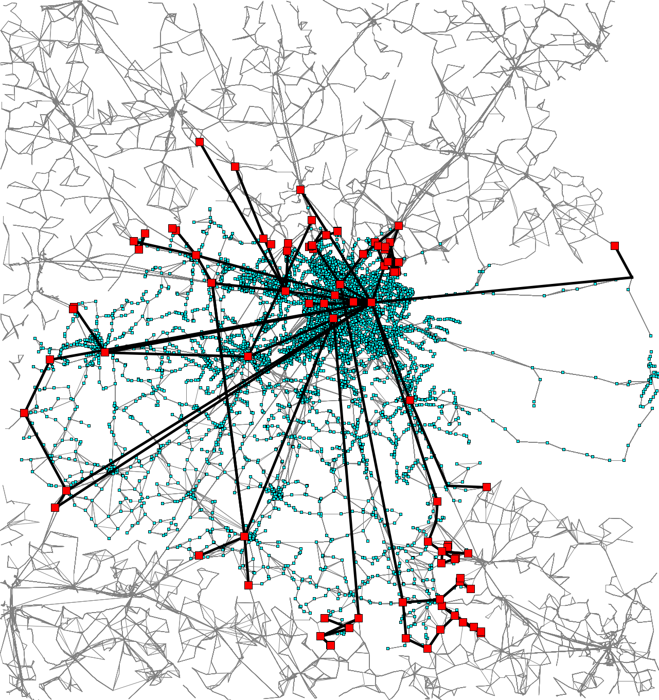
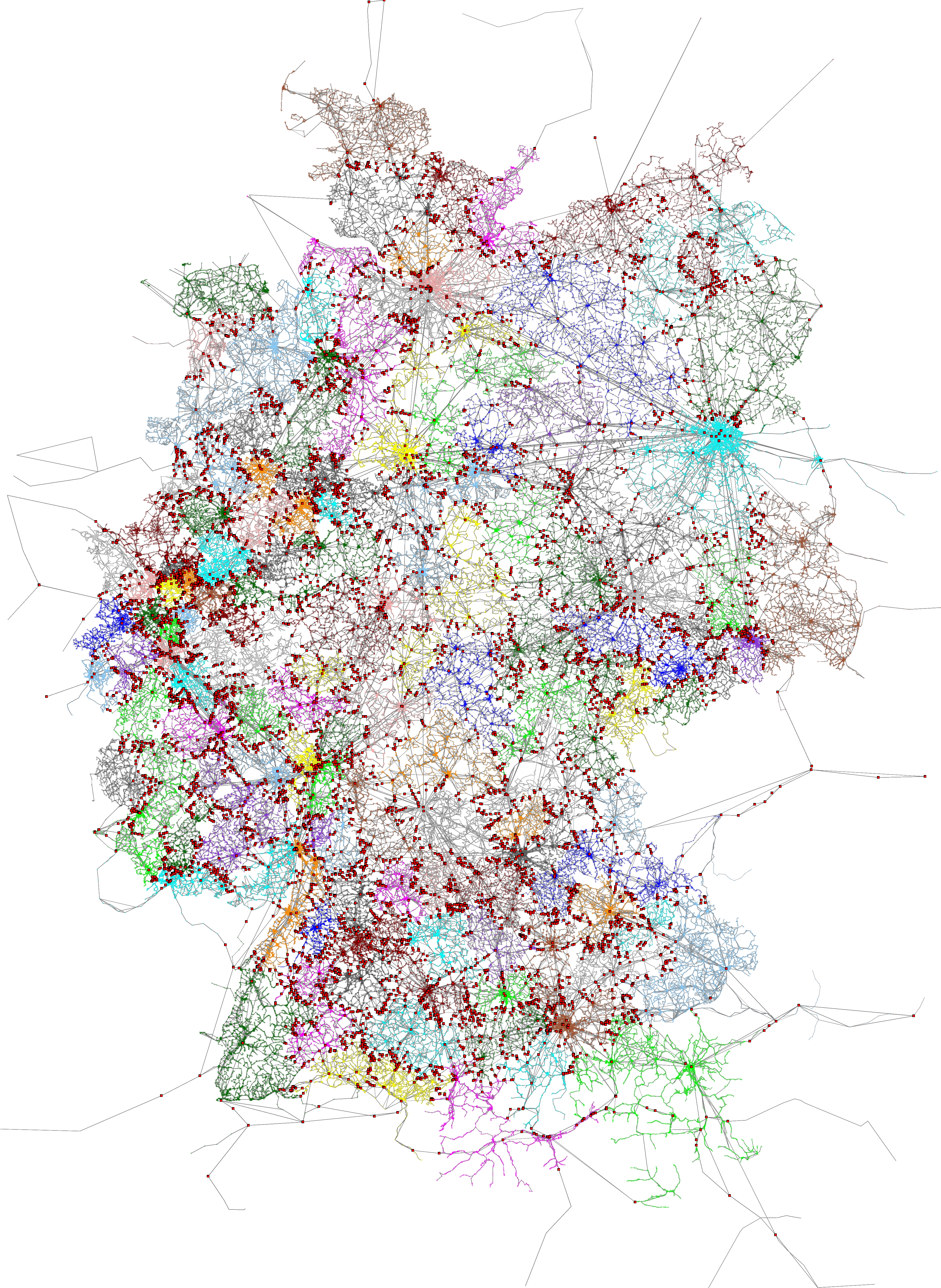
Examples of classical approaches. On the left is a map view showing average velocity vectors over the period from 1997 to 2001[1]. On the right you can see a time versus eastward (longitudinal) position plot for a single station.

Each of these approaches have proved to be informative ways to understand the spatial distribution of crustal movements and the time evolution of solid earth deformation. However, because geodetic shifts happen in almost imperceptible distances (mm) and over long timescales, both approaches can only show a small subset of the data at any time—a condensed average velocity per station, or a detailed view of a single station, respectively. Our visualization enables a scientist to see all the data at once, then interactively drill down to a specific subset of interest.

Our visualization approach is straightforward; by magnifying the daily longitude and latitude position changes, we show tracks of the evolution of the position of each station. These magnified position tracks are shown as trails on top of a shaded relief topography to provide a sense of position evolution in geographic context.

To see how it works in practice, let’s step through an an example. Consider this tiny set of longitude/latitude pairs for a single GNSS station, with the differing digits shown in bold:

Day Index
Longitude
Latitude
0
139.06990407
34.949757897
1
139.06990400
34.949757882
2
139.06990413
34.949757941
3
139.06990409
34.949757921
4
139.06990413
34.949757904

If we were to draw line segments between these points directly on a map, they’d be much too small to see at any reasonable scale. So we take these minute differences and multiply them by a user-controlled scaling factor. By default this factor is 105.5 (about 316,000x).

To help the user identify which end is the start of the line, we give the start and end points different colors and interpolate between them. Blue and red are the default colors, but they’re user-configurable. Although day-to-day movement of stations may seem erratic, by using this method, one can make out a general trend in the relative motion of a station.
Close-up of a single station’s movement during the three year period from 2003 to 2006.

However, static renderings of this sort suffer from the same problem that velocity vector images do; in regions with a high density of GNSS stations, tracks overlap significantly with one another, obscuring details. To solve this problem, our visualization lets the user interactively control the time range of interest, the amount of amplification and other settings. In addition, by animating the lines from start to finish, the user gets a real sense of motion that’s difficult to achieve in a static image.

We’ve applied our new visualization to the ~20 years of data from the GEONET array in Japan. Through it, we can see small but coherent changes in direction before and after the great 2011 Tohoku earthquake.
GPS data sets (in .json format) for both the GEONET data in Japan and the Plate Boundary Observatory (PBO) data in the western US are available at earthquake.rc.fas.harvard.edu.

This short animation shows many of the visualization’s interactive features. In order:
  1. Modifying the multiplier adjusts how significantly the movements are magnified.
  2. We can adjust the time slider nubs to select a particular time range of interest.
  3. Using the map controls provided by the Google Maps JavaScript API, we can zoom into a tiny region of the map.
  4. By enabling map markers, we can see information about individual GNSS stations.
By focusing on a stations of interest, we can even see curvature changes in the time periods before and after the event.
Station designated 960601 of Japan’s GEONET array is located on the island of Mikura-jima. Here we see the period from 2006 to 2012, with movement magnified 105.1 times (126,000x).

To achieve fast rendering of the line segments, we created a custom overlay using THREE.js to render the lines in WebGL. Data for the GNSS stations is passed to the GPU in a data texture, which allows our vertex shader to position each point on-screen dynamically based on user settings and animation.

We’re excited to continue this productive collaboration between Harvard and Google as we explore opportunities for groundbreaking, new earthquake visualizations. If you’d like to try out the visualization yourself, follow the instructions at earthquake.rc.fas.harvard.edu. It will walk you through the setup steps, including how to download the available data sets. If you’d like to report issues, great! Please submit them through the GitHub project page.

Acknowledgments

We wish to thank Bill Freeman, a researcher on Machine Perception, who hatched the idea and developed the initial prototypes, and Fernanda Viégas and Martin Wattenberg of the Big Picture Team for their visualization design guidance.

References

[1] Loveless, J. P., and Meade, B. J. (2010). Geodetic imaging of plate motions, slip rates, and partitioning of deformation in Japan, Journal of Geophysical Research.


An Update on fast Transit Routing with Transfer Patterns


What is the best way to get from A to B by public transit? Google Maps is answering such queries for over 20,000 cities and towns in over 70 countries around the world, including large metro areas like New York, São Paulo or Moscow, and some complete countries, such as Japan or Great Britain.
Since its beginnings in 2005 with the single city of Portland, Oregon, the number of cities and countries served by Google’s public transit directions has been growing rapidly. With more and larger regions, the amount of data we need to search in order to provide optimal directions has grown as well. In 2010, the search speed of transit directions made a leap ahead of that growth and became fast enough to update the result while you drag the endpoints. The technique behind that speed-up is the Transfer Patterns algorithm [1], which was created at Google’s engineering office in Zurich, Switzerland, by visiting researcher Hannah Bast and a number of Google engineers.

I am happy to report that this research collaboration has continued and expanded with the Google Focused Research Award on Next-Generation Route Planning. Over the past three years, this grant has supported Hannah Bast’s research group at the University of Freiburg, as well as the research groups of Peter Sanders and Dorothea Wagner at the Karlsruhe Institute of Technology (KIT).

From the project’s numerous outcomes, I’d like to highlight two recent ones that re-examine the Transfer Patterns approach and massively improve it for continent-sized networks: Scalable Transfer Patterns [2] and Frequency-Based Search for Public Transit [3] by Hannah Bast, Sabine Storandt and Matthias Hertel. This blogpost presents the results from these publications.

The notion of a transfer pattern is easy to understand. Suppose you are at a transit stop downtown, call it A, and want to go to some stop B as quickly as possible. Suppose further you brought a printed schedule book but no smartphone. (This sounded plausible only a few years ago!) As a local, you might know that there are only two reasonable options:
  1. Take a tram from A to C, then transfer at C to a bus to B.
  2. Take the direct bus from A to B, which only runs infrequently.
We say the first option has transfer pattern A-C-B, and the second option has transfer pattern A-B. Notice that no in-between stops are mentioned. This is very compact information, much less than the actual schedules, but it makes looking up the schedules significantly faster: Knowing that all optimal trips follow one of these patterns, you only need to look at those lines in the schedule book that provide direct connections from A to C, C to B and A to B. All other lines can safely be ignored: you know you will not miss a better option.

While the basic idea of transfer patterns is indeed that simple, it takes more to make it work in practice. The transfer patterns of all optimal trips have to be computed ahead of time and stored, so that they are available to answer queries. Conceptually, we need transfer patterns for every pair of stops, because any pair could come up in a query. It is perfectly reasonable to compute them for all pairs within one city, or even one metro area that is densely criss-crossed by a transit network comprising, say, a thousand stops, yielding a million of pairs to consider.

As the scale of the problem increases from one metro area to an entire country or continent, this “all pairs” approach rapidly becomes expensive: ten thousand stops (10x more than above) already yield a hundred million pairs (100x more than above), and so on. Also, the individual transfer patterns become quite repetitive: For example, from any stop in Paris, France to any stop in Cologne, Germany, all optimal connections end up using the same few long-distance train lines in the middle, only the local connections to the railway stations depend on the specific pair of stops considered.

However, designated long-distance connections are not the only way to travel between different local networks – they also overlap and connect to each other. For mid-range trips, there is no universally correct rule when to choose a long-distance train or intercity bus, short of actually comparing options with local or regional transit, too.

The Scalable Transfer Patterns algorithm [2] does just that, but in a smart way. For starters, it uses what is known as graph clustering to cut the network into pieces, called clusters, that have a lot of connections inside but relatively few to the outside. As an example, the figure below (kindly provided by the authors) shows a partitioning of Germany into clusters. The stops highlighted in red are border stops: They connect directly to stops outside the cluster. Notice how they are a small fraction of the total network.
The public transit network of Germany (dots and lines), split into clusters (shown in various colors). Of all 251,763 stops, only 10,886 (4.32%) are boundary stops, highlighted as red boxes. Click here to view the full resolution image.[source: S. Storandt, 2016]
Based on the clustering, the transfer patterns of all optimal connections are computed in two steps.

In step 1, transfer patterns are computed for optimal connections inside each cluster. They are stored for query processing later on, but they also accelerate the search through a cluster in the following step: between the stops on its border, we only need to consider the connections captured in the transfer patterns.

The next figure sketches how the transit network in the cluster around Berlin gets reduced to much fewer connections between border stations. (The central station stands out as a hub, as expected. It is a border station itself, because it has direct connections out of the cluster.)
The cluster of public transit connections around Berlin (shown as dots and lines in light blue), its border stops (highlighted as red boxes), and the transfer patterns of optimal connections between border stops (thick black lines; only the most important 111 of 592 are shown to keep the image legible). This cuts out 96.15% of the network (especially a lot of the high-frequency inner city trips, which makes the time savings even bigger). Click here to view the full resolution image. [source: S. Storandt, 2016]
In step 2, transfer patterns can be computed for the entire network, that is, between any pair of clusters. This is done with the following twists:

  • It suffices to consider trips from and to boundary stops of any cluster; the local transfer patterns from step 1 will supply the missing pieces later on.
  • The per-cluster transfer patterns from step 1 greatly accelerate the search across other clusters.
  • The search stops exploring any possible connection between two boundary stops as soon as it gets worse than a connection that sticks to long-distance transit between clusters (which may not always be optimal, but is always quick to compute).

The results of steps 1 and 2 are stored and used to answer queries. For any given query from some A to some B, one can now easily stitch together a network of transfer patterns that covers all optimal connections from A to B. Looking up the direct connections on that small network (like in the introductory example) and finding the best one for the queried time is very fast, even if A and B are far away.

The total storage space needed for this is much smaller than the space that would be needed for all pairs of stops, all the more the larger the network gets. Extrapolating from their experiments, the researchers estimate [2] that Scalable Transfer Patterns for the whole world could be stored in 30 GB, cutting their estimate for the basic Transfer Patterns by a thousand(!). This is considerably more powerful than the “hub station” idea from the original Transfer Patterns paper [1].

The time needed to compute Scalable Transfer Patterns is also estimated to shrink by three orders of magnitude: At a high level, the earlier phases of the algorithm accelerate the later ones, as described above. At a low level, a second optimization technique kicks in: exploiting the repetitiveness of schedules in time. Recall that finding transfer patterns is all about finding the optimal connections between pairs of stops at any possible departure time.

Frequency-based schedules (e.g., one bus every 10 minutes) cause a lot of similarity during the day, although it often doesn’t match up between lines (e.g., said bus runs every 10 minutes before 6pm and every 20 minutes after, and we seek connections to a train that runs every 12 minutes before 8pm and every 30 minutes after). Moreover, this similarity also exists from one day to the next, and we need to consider all permissible departure dates.

The Frequency-Based Search for Public Transit [3] is carefully designed to find and take advantage of repetitive schedules while representing all one-off cases exactly. Comparing to the set-up from the original Transfer Patterns paper [1], the authors estimate a whopping 60x acceleration of finding transfer patterns from this part alone.

I am excited to see that the scalability questions originally left open by [1] have been answered so convincingly as part of this Focused Research Award. Please see the list of publications on the project’s website for more outcomes of this award. Besides more on transfer patterns, they contain a wealth of other results about routing on road networks, transit networks, and with combinations of travel modes.

References:

[1] Fast Routing in Very Large Public Transportation Networks Using Transfer Patterns
by H. Bast, E. Carlsson, A. Eigenwillig, R. Geisberger, C. Harrelson, V. Raychev and F. Viger
(ESA 2010). [doi]

[2] Scalable Transfer Patterns
by H. Bast, M. Hertel and S. Storandt (ALENEX 2016). [doi]

[3] Frequency-based Search for Public Transit
by H. Bast and S. Storandt (SIGSPATIAL 2014). [doi]

Simulating fermionic particles with superconducting quantum hardware


Digital quantum simulation is one of the key applications of a future, viable quantum computer. Researchers around the world hope that quantum computing will not only be able to process certain calculations faster than any classical computer, but also help simulate nature more accurately and answer longstanding questions with regard to high temperature superconductivity, complex quantum materials, and applications in quantum chemistry.

A crucial part in describing nature is simulating electrons. Without electrons, you cannot describe metals and their conductivity, or the interatomic bonds which hold molecules together. But simulating systems with many electrons makes for a very tough problem on classical computers, due to some of their peculiar quantum properties.

Electrons are fermionic particles, and as such obey the well-known Pauli exclusion principle which states that no fermions in a system can occupy the same quantum state. This is due to a property called anticommutation, an inherent quantum mechanical behavior of all fermions, that makes it very tricky to fully simulate anything that is composed of complex interactions between electrons. The upshot of this anticommutative property is that if you have identical electrons, one at position A and another at position B, and you swap them, you end up with a different quantum state. If your simulation has many electrons you need to carefully keep track of these changes, while ensuring all the interactions between electrons can be completely, yet separately tunable.

Add to that the memory errors caused by fluctuation or noise from their environment and the fact that quantum physics prevents one from directly monitoring the superconducting quantum bits (“qubits”) of a quantum computer directly to account for those errors, and you've got your hands full. However, earlier this year we reported on some exciting steps towards Quantum Error Correction - as it turns out, the hardware we built isn't only useable for error correction, but can also be used for quantum simulation.

In Digital quantum simulation of fermionic models with a superconducting circuit, published in Nature Communications, we present digital methods that enable the simulation of the complex interactions between fermionic particles, by using single-qubit and two-qubit quantum logic gates as building blocks. And with the recent advances in hardware and control we can now implement them.

We took our qubits and made them act like interacting fermions. We experimentally verified that the simulated particles anticommute, and implemented static and time-varying models. With over 300 logic gates, it is the largest digital quantum simulation to date, and the first implementation in a solid-state device.
Left: Model picture with four fermionic modes in two sites. The modes are occupied or unoccupied. For example, we can start with two fermionic particles in the right well, by occupying the blue and green mode. If the particles repel each other, there's a good chance that one of the them will hop to the left well through the process of quantum tunneling through the barrier. It will then occupy the red or purple mode. This interplay of on-site interaction and hopping lies at the core of describing processes in physics and chemistry, ranging from the conductivity of metals to the binding between atoms in molecules. Right: The false-colored cross-shaped structures are the superconducting quantum bits. The colors correspond to the modes, so if we have two fermionic particles in the blue and red modes, the rightmost two quantum bits are excited.
Coming up with an efficient sequence of logic gates that can accurately model the interactions for systems of fermions wasn’t easy. So we teamed up with Dr. Lucas Lamata, M.Sc. Laura García-Álvarez, and Prof. Enrique Solano from the QUTIS group at the University of the Basque Country (UPV/EHU) in Bilbao, Spain, who are experts in constructing algorithms and translating them into the streams of logic gates we can implement with our hardware.

For the future, digital quantum simulation holds the promise that it can be run on an error-corrected quantum computer. But before that, we foresee the construction of larger testbeds for simulation with improvements in logic gates and architecture. This experiment is a critical step on the path to creating a quantum simulator capable of modeling fermions as well as bosons (particles which can be interchanged, as opposed to fermions), opening up exciting possibilities for simulating physical and chemical processes in nature.